This is my "Diversion" page where I give you excuses why I have lapses in building the O'Bannon.
I just got off a three week training tour in which we trained many people about tower cranes (my profession) and how they work. We spent a lot of time explaining how these cranes grow with the building as it gets higher. I saw the bewilderment in the eyes of our students even after some of our explanation. The questionable looks subsided, for the most part, after we went in to more detail. But reflecting on our teaching, I knew even during these classes what we need is a working model of at least the climbing portion of a tower crane.
I spent some time thinking of what key parts would be required to make this model and I easily focused in on the one single part instrumental to make a working model. The hydraulic cylinder is key to this models success. I knew if I could find a scale, dual acting, cylinder that I would have the one vital part to make this work. The rest is just fabrication.
I did some searching, and Google soon had me with several possible sources. I found the cylinder and now I can start making mast sections and after a run of these, I will make the single, hydraulically operated, climbing section that will allow this model to be fully demonstrated.
Below, you will see progress on this diversion. I hope to get this done and get back on the O'Bannon soon as spring is nearly here and I want to get some sea trials in on the working hull.
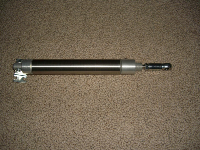
Here is the cylinder that is key to building this working model.
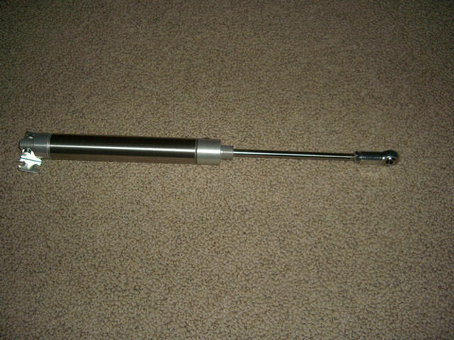
This cylinder will raise the crane model one stroke at a time.
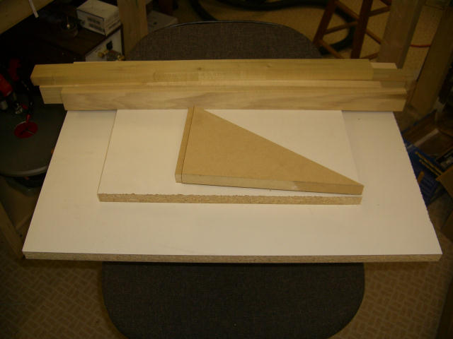
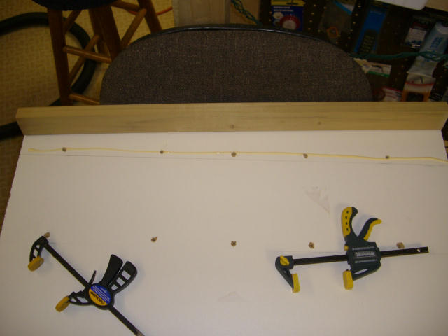
Raw material for mast jig.
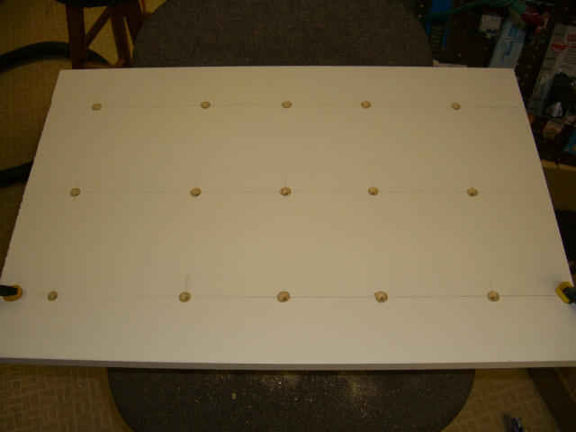
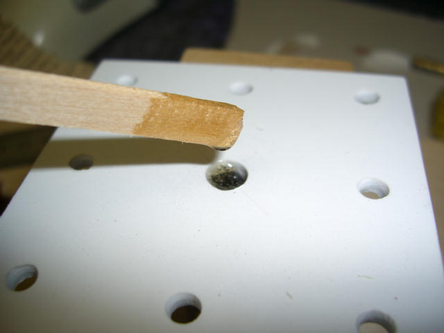
Countersunk holes for screws to secure the hardwood cleats to assure the jig stays flat and square.
First slat being "glued & Screwed" in place.
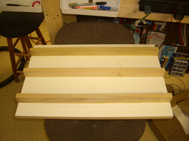
The remainder of the hardwood slats now secure.
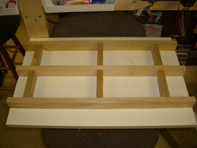
Cross bracing to further insure a flat and level mast jig.
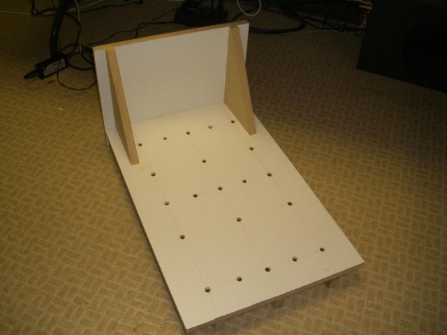
The 90 degree upright now secured in place.
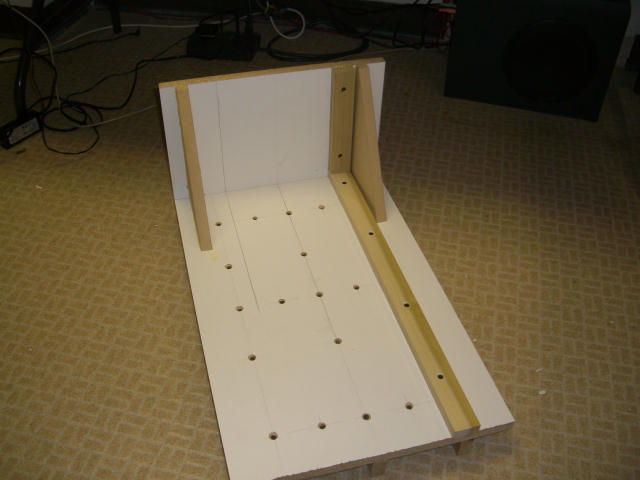
A hardwood reference rail is fastened to the jig.
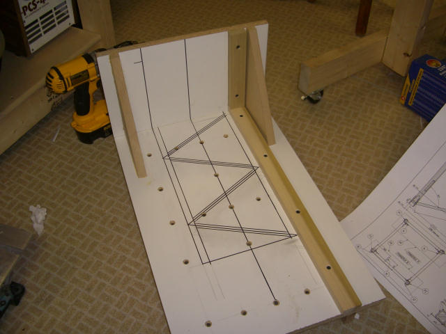
The mast geometry is drawn in place. There will be an additional rail on the left side that will press everything to the reference rail.

This is the start of the main chord jig. Again, hardwood is used to minimize any warping. This jig will allow me to drill precise and consistent holes in the main chords so each chord will fit, and pin properly, to the next one. I HOPE!
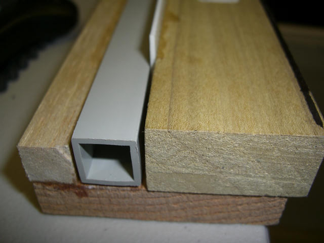
The jig will require a space left on each face of the main chords. Here, spacers are being inserted and glued to the jig.
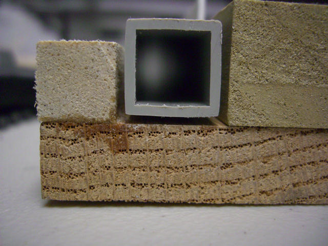
Here you can see the spacing around the chord.
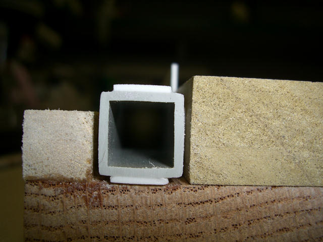
Now the main chord has the added thickner plates to give the pin holes more material around them.
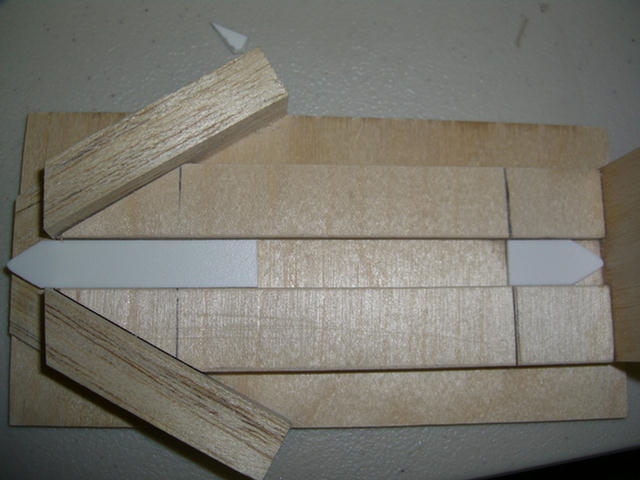
This jig is for the thickening plates at each end of the main chord. Holes will be bored through these plates to connect one mast section to another.
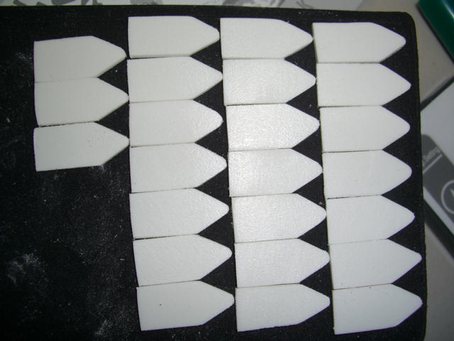
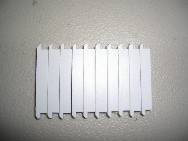
24 down, 152 more to go. YIKES!
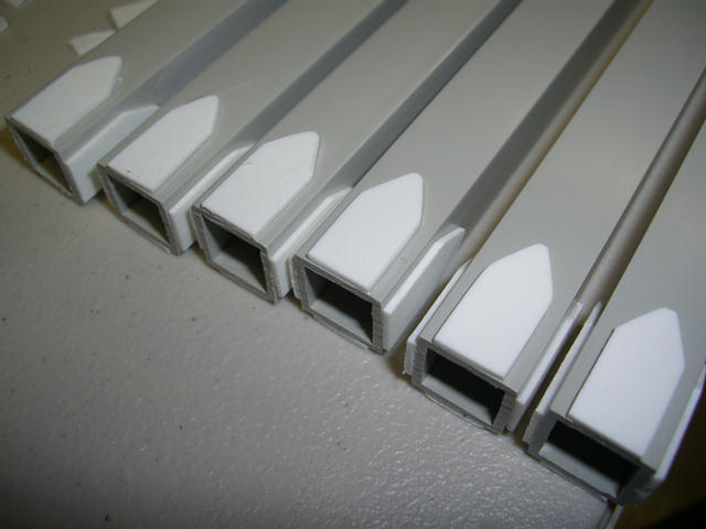
The start of the main chords.

The joints need to be strong so I am going to double the thickness at this end.
Slide this in and glue it so it is one with the chord.
Now to sand it flush with the chord.
Now, let's bore the holes for the pins.
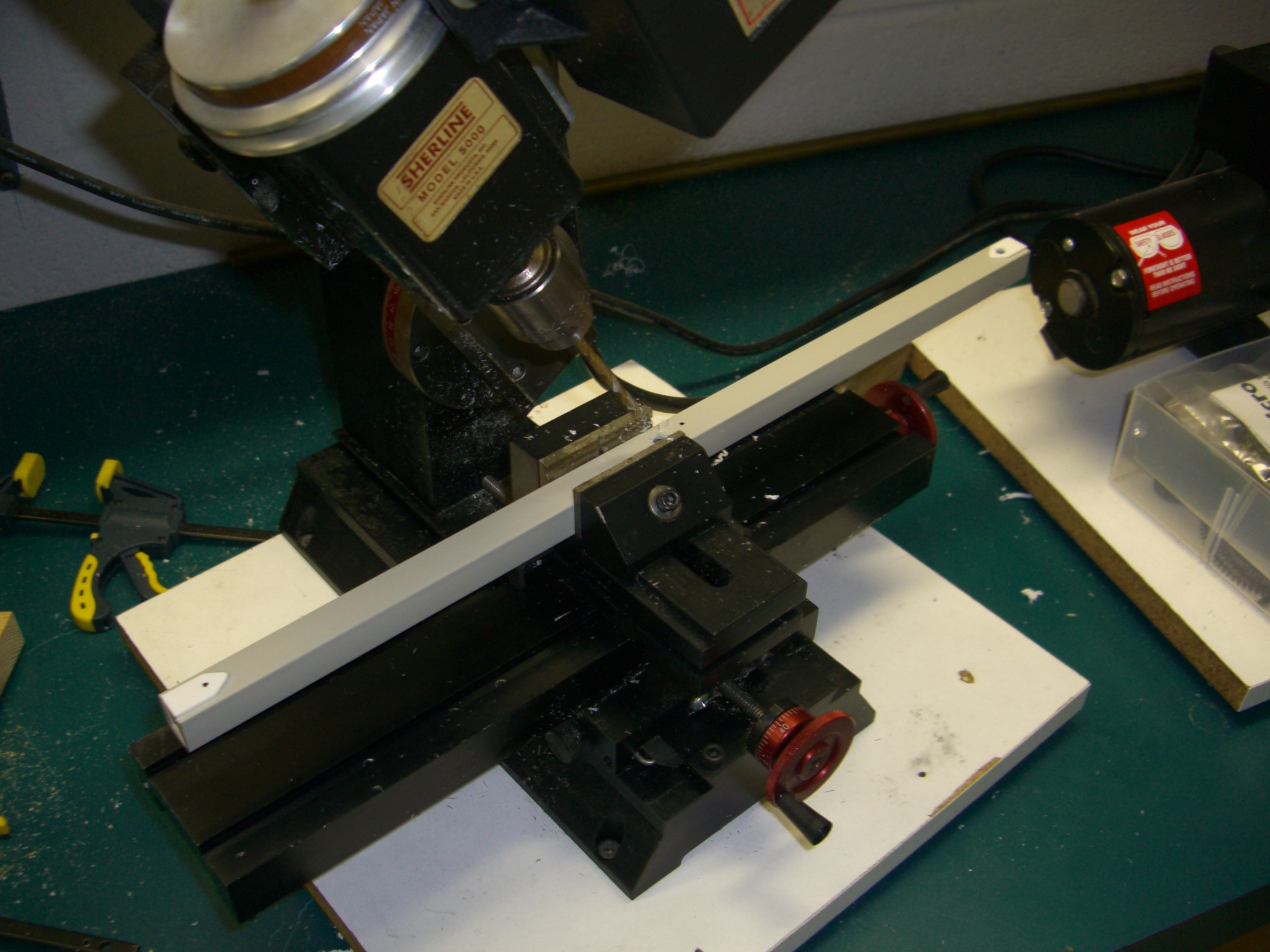
Jig to bore holes in end of main chords.
A resounding.................FAILURE!!
Could the bit have wondered having to bore through all that wood?
Both sets of holes are off center............................. Back to the drawing board.
I'm going to not use the wood to drill through. I will bore directly in the end of the chord set up in the jig.
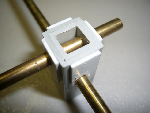
The pins cross each other well so the up/down spacing is O. K., but I will have to get the holes consistently in the center of the chord or one chord will not pin up to the next one.
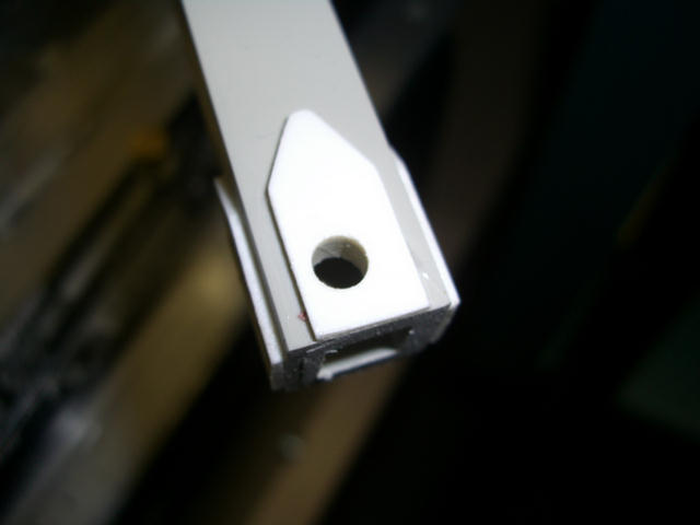
This one came out great, but I don't know if I can turn out 16 of them to be identical.
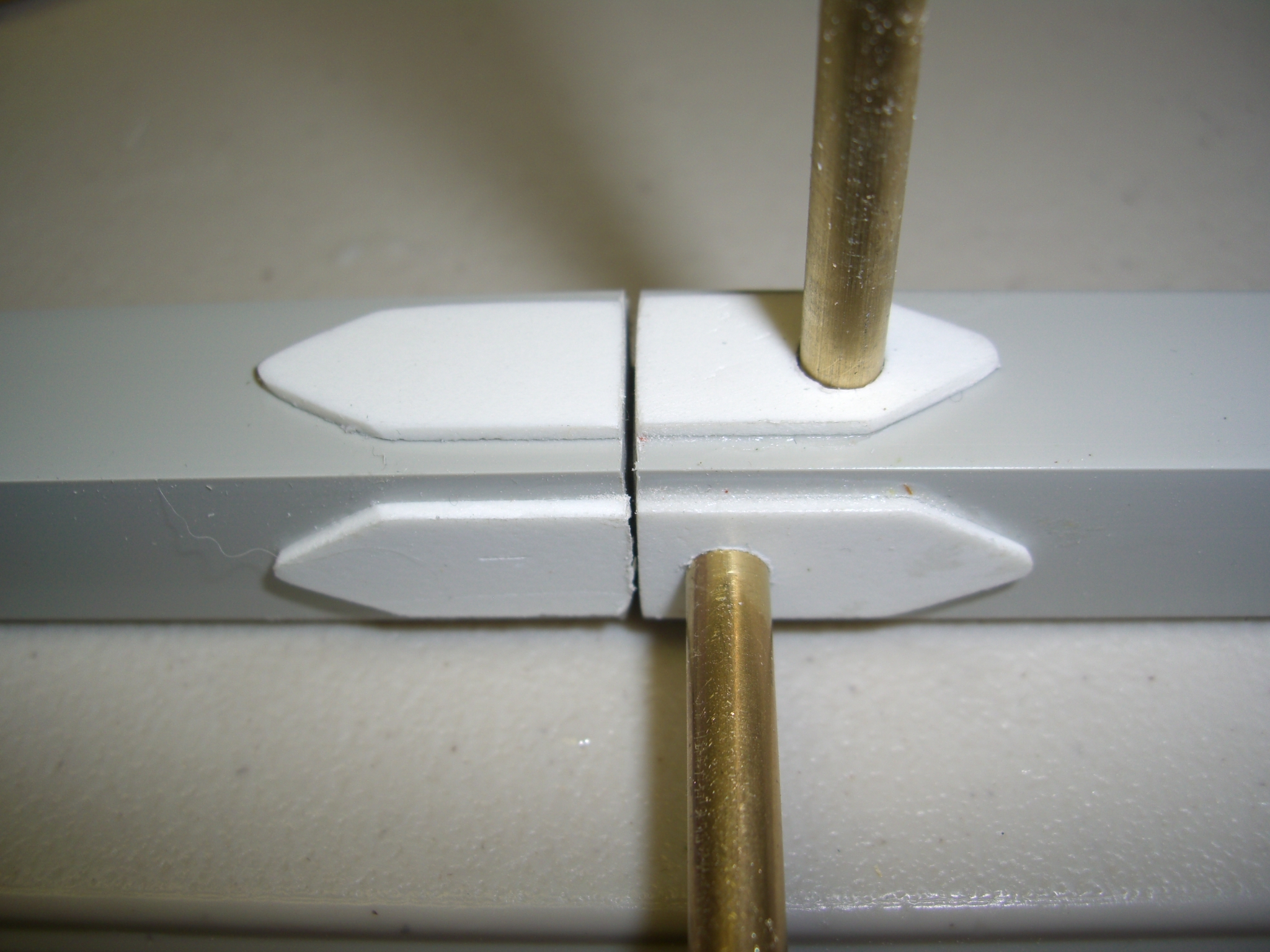
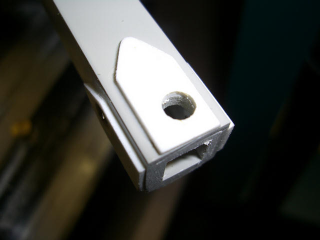
Here are the two chords pinned together.
These are the climbing lugs I machined for the mast sections. The Climbing cage will push off of these to raise the crane.
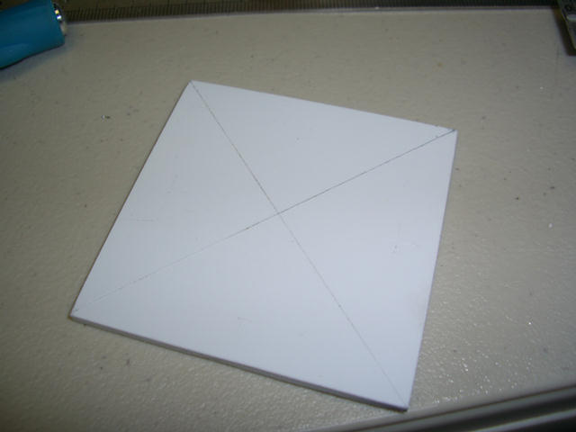
The start of one of the four base plates required.
Adding the gussets.
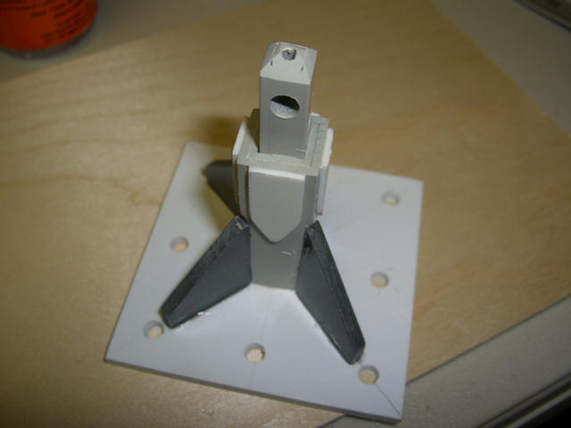
More gusseting.
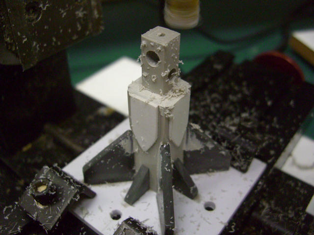
Some final machining.
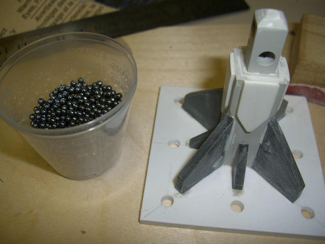
I guess I can be pretty anal, but this part needs to have some "scale weight" to it, so....
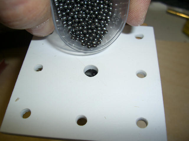
I'm adding some lead shot to bring these up to the robust weight they should be.
Capped off with an epoxy plug.
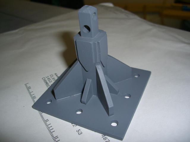
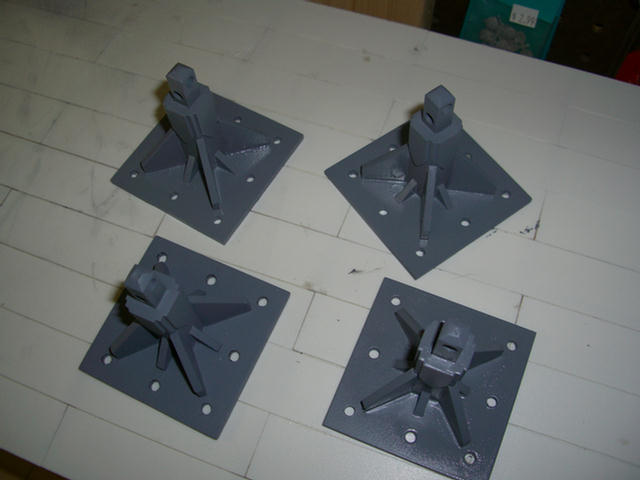
One of four primed and ready for the final color coat.
Taa-Daa!!
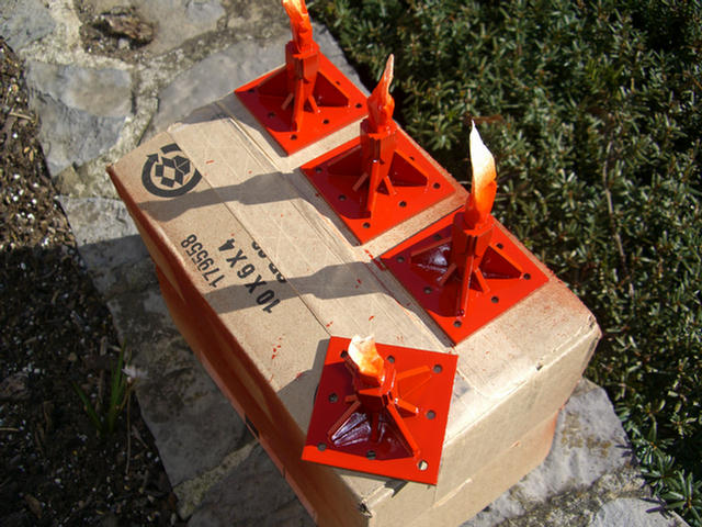
Painted red and ready for use.
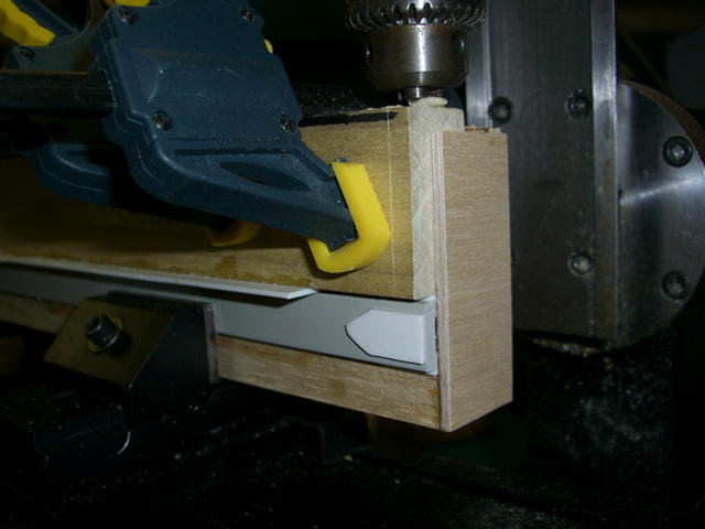
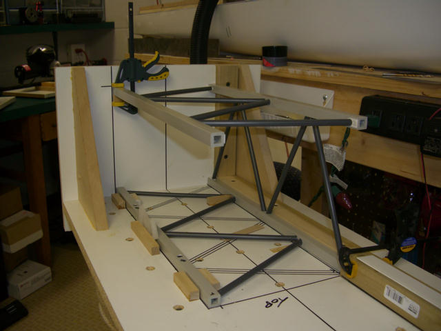
Drilling pilot holes for lattice tubes.
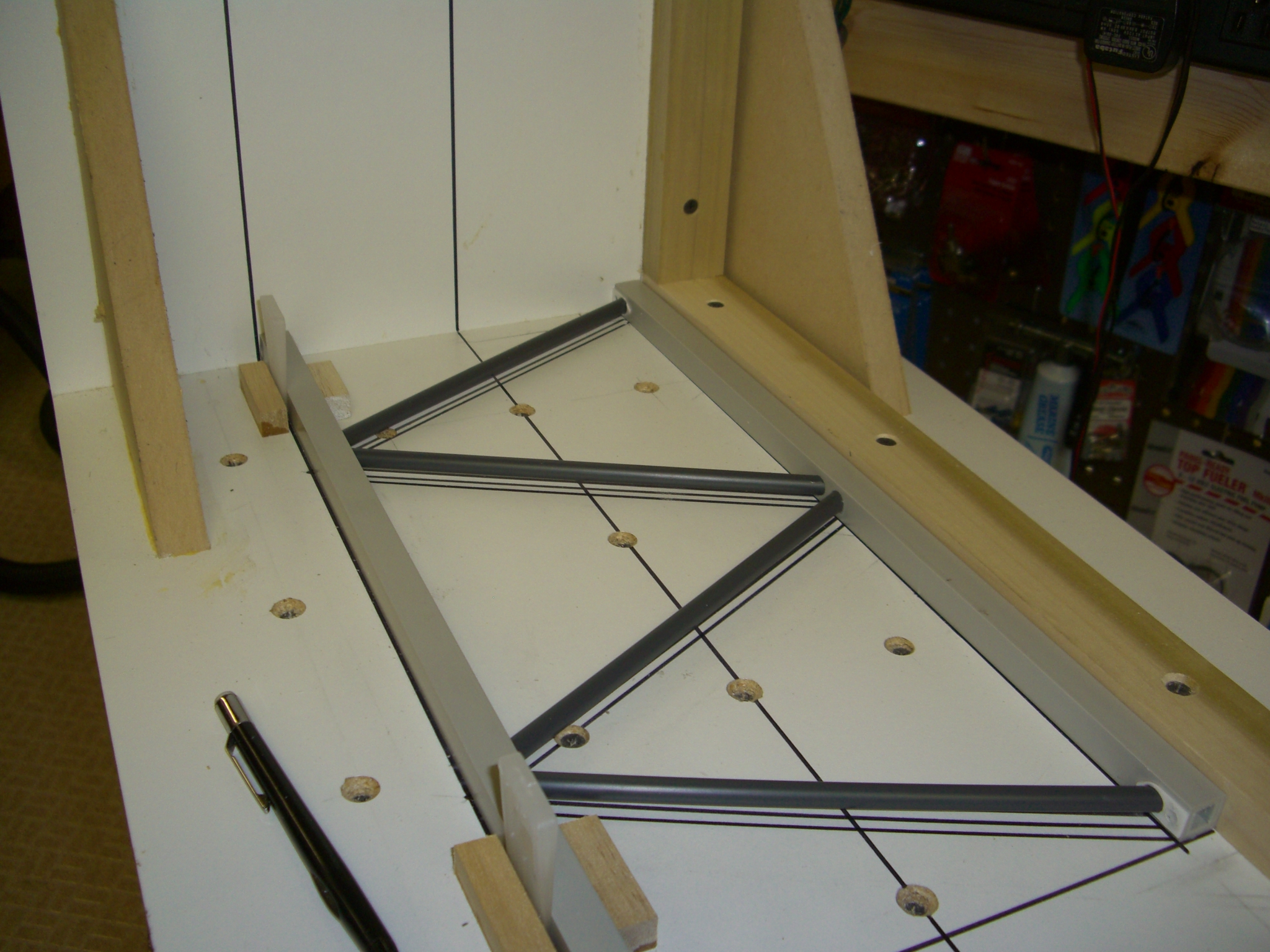
First components loosely fitted into the tower jig.
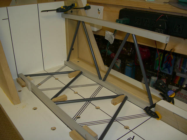
The second panel fitted into place.
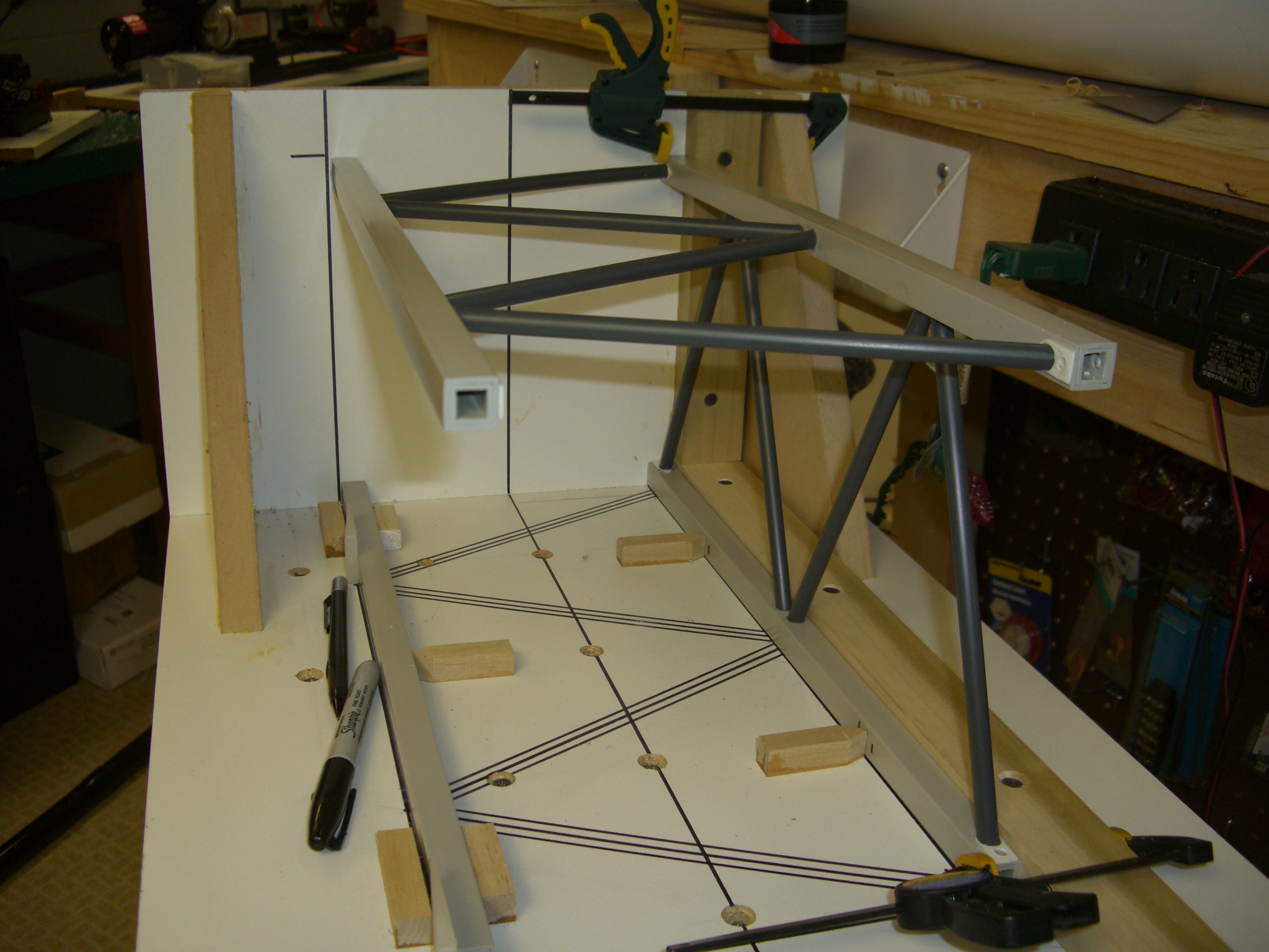
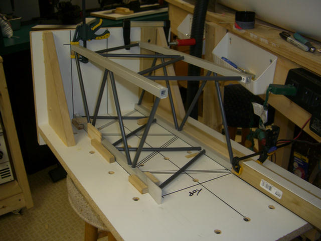
The start of the third panel. That's it for today. :(
The third set of lacings being installed.
The final side.
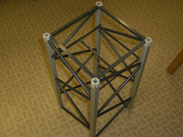
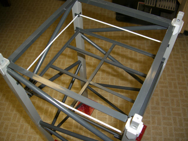
Here is the top frame and just below is the start of the mast platform.
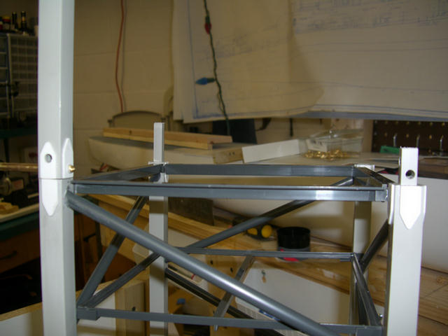
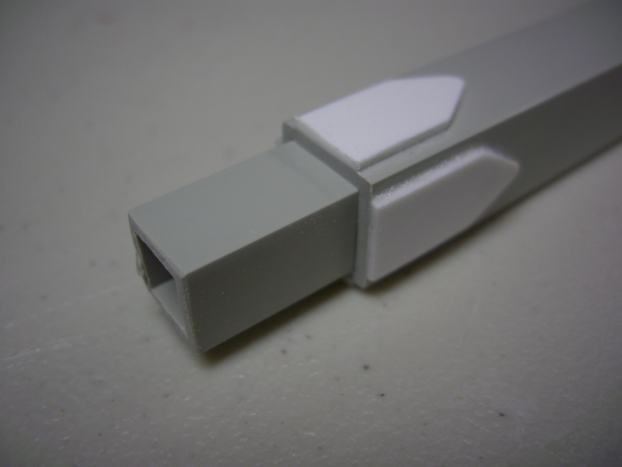
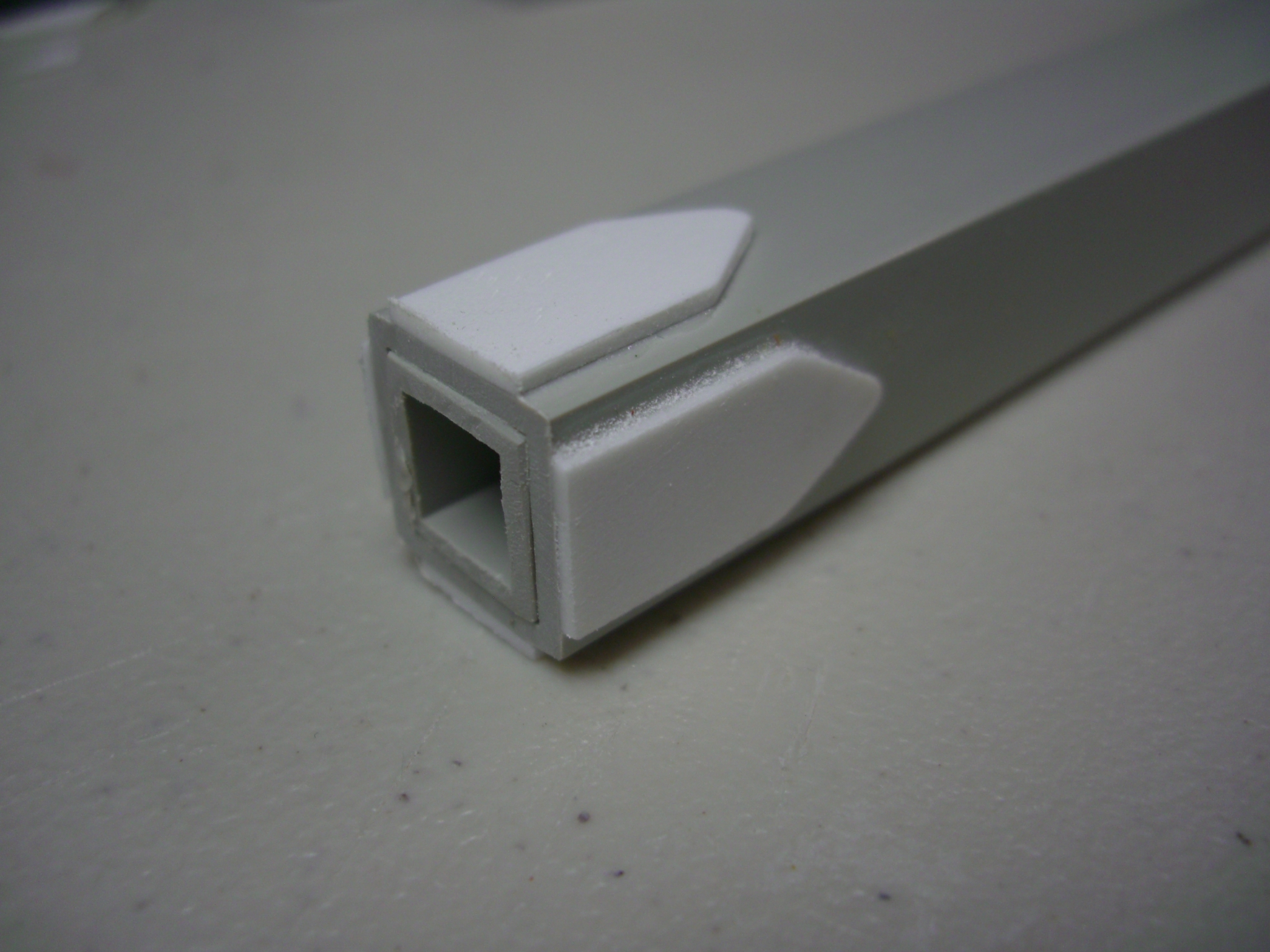
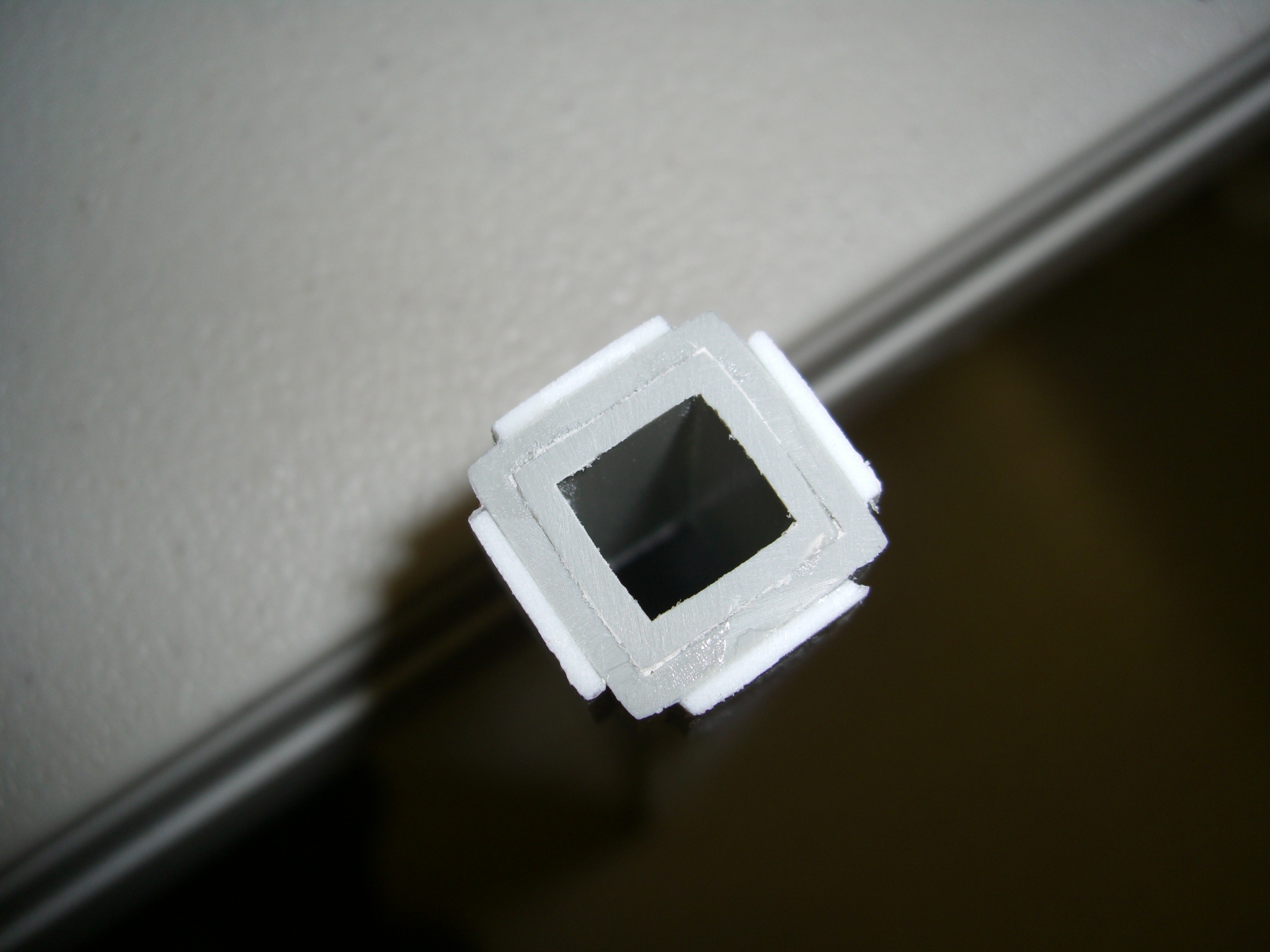
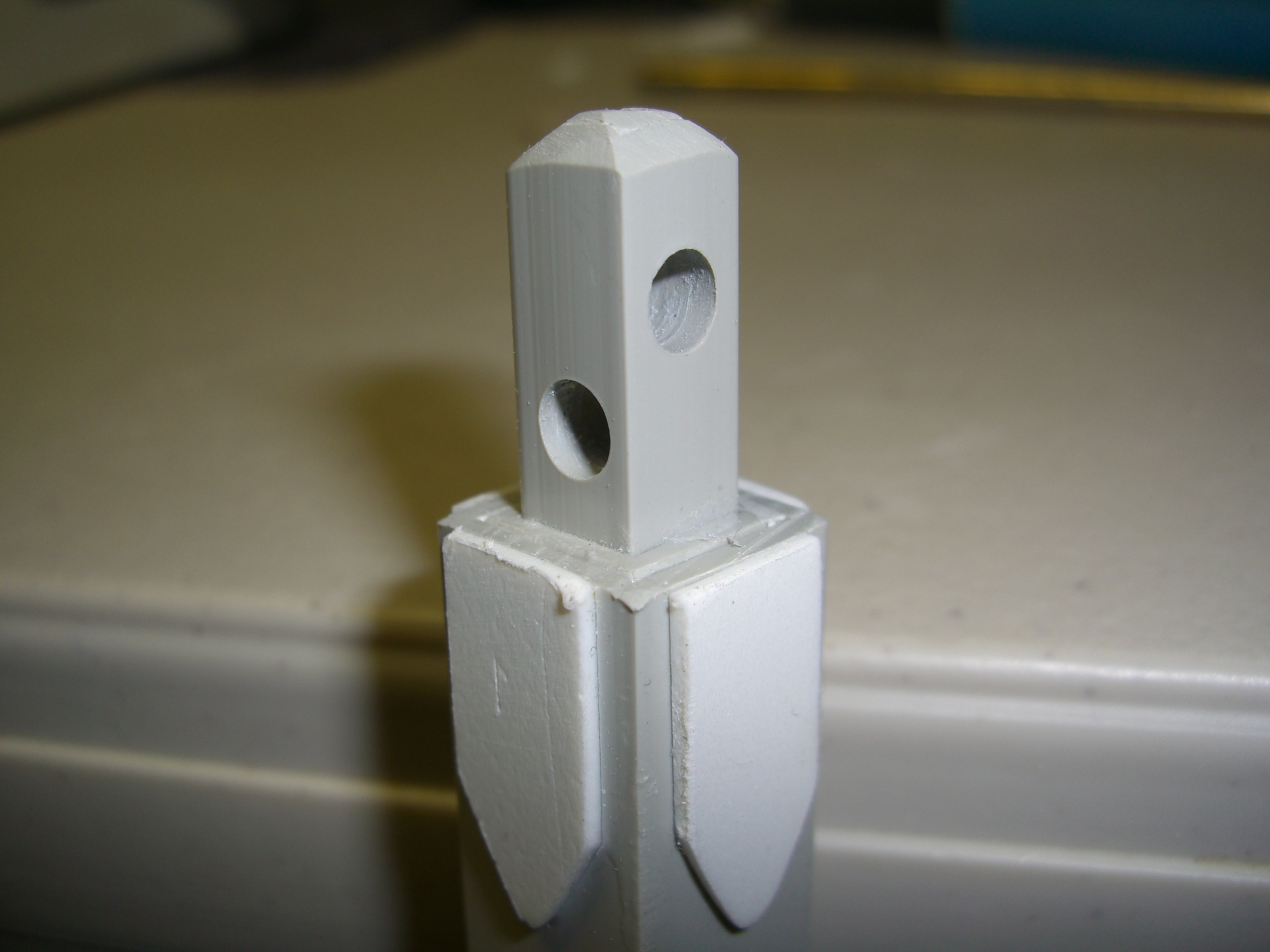
Here is the installation of the mast connector inserts.
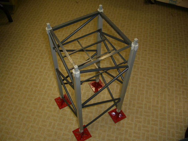
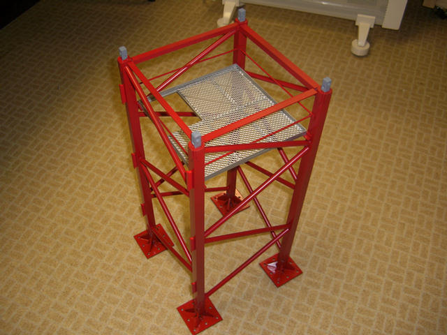
The feet are on the bottom of the mast and the platform only lacks the expanded metal floor.
Here the mid rail has been installed.
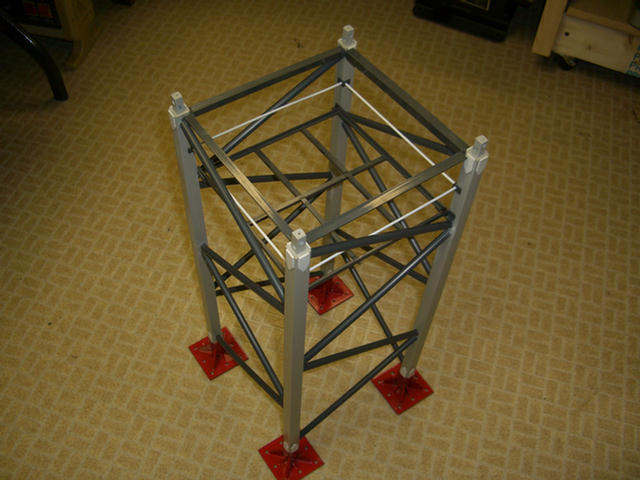
This thing is almost ready for the paint shop.
It's been 15 hours..........That's it for today.
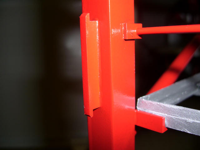
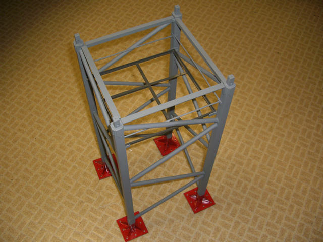
Climbing lugs that support the upper crane's weight during the climbing process.
Rest platform in place. I still need to build the ladder inside the mast.
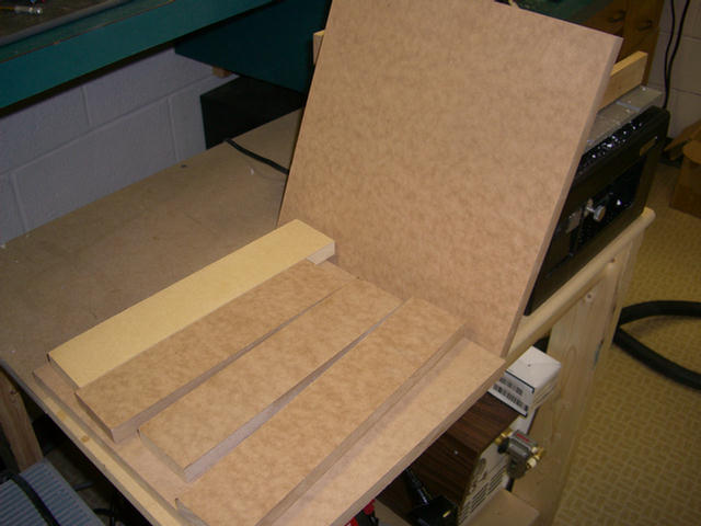
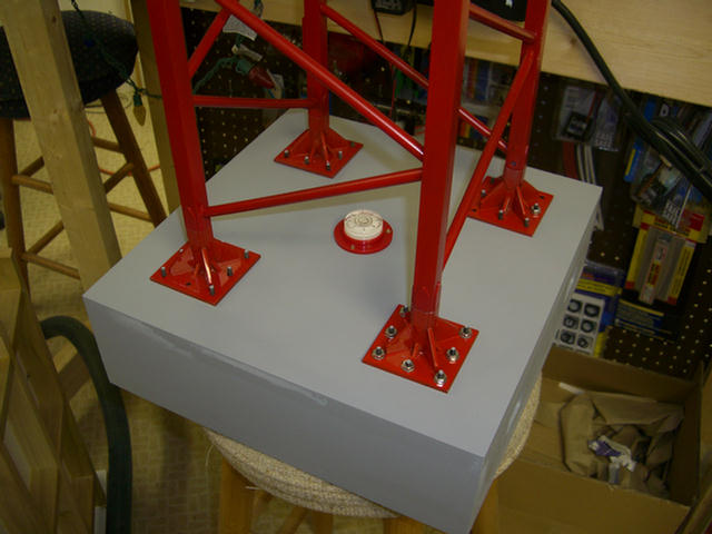
Pieces for the base of the model that will appear like a concrete foundation when finished.
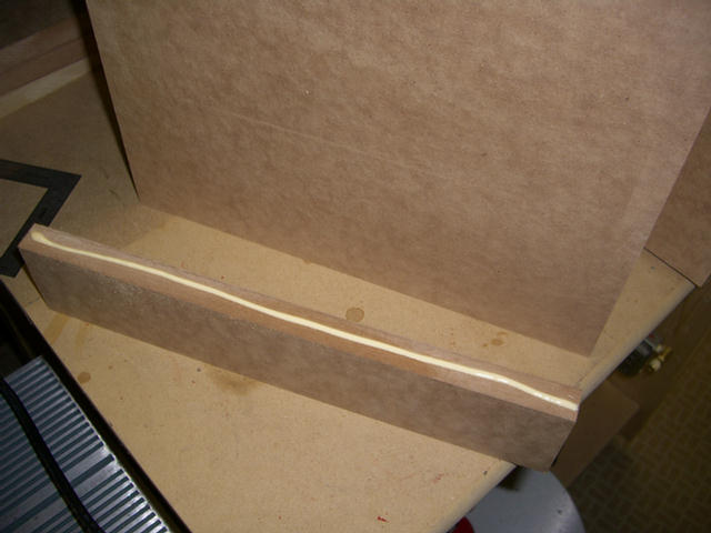
First side has glue and is ready to attach.
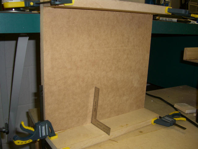
Squared up and clamped.
Adding the blocks to form a stop for the removable front panel.
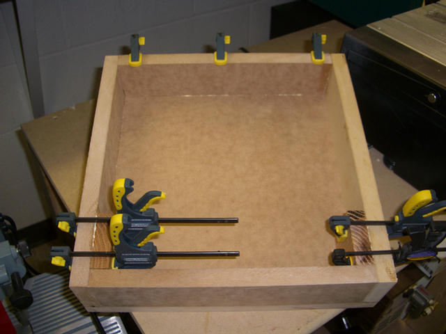
Gluing the top in place. The front panel will be removable to gain access to the inside for the air compressor and storage
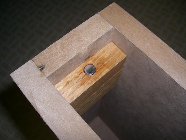
Rare earth disc magnet is so strong I will use a very small piece of steel on the panel to hold it in place.
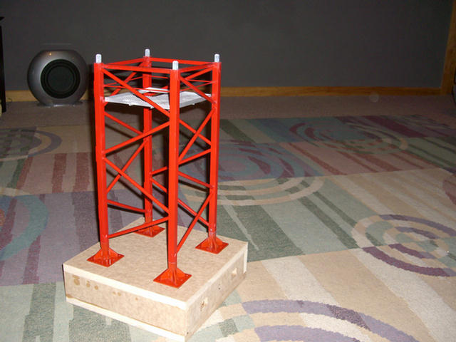
Still need to sand, fill, and paint to appear as a concrete foundation.
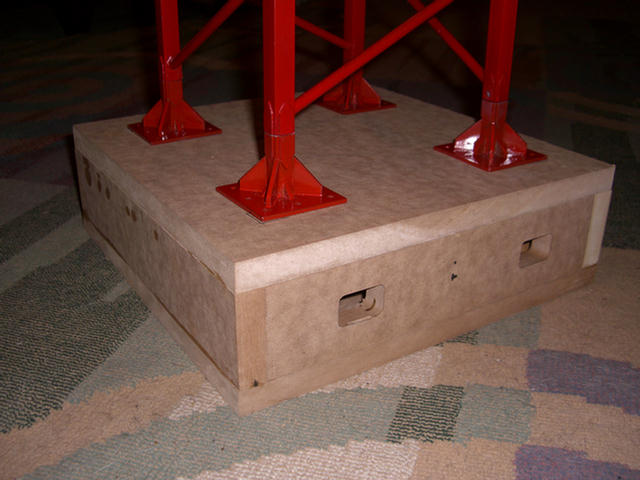
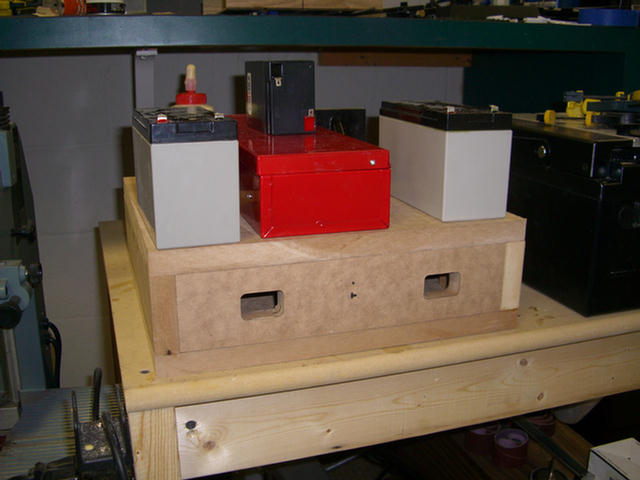
Finger holes to remove panel to gain access to compressor and on-off switch.
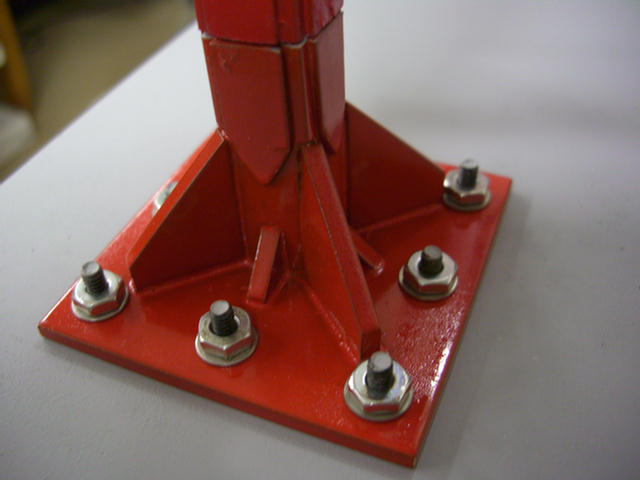
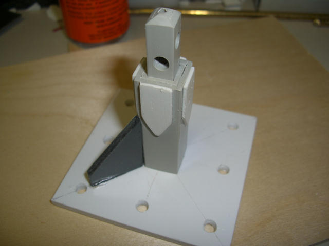
Anchor stool bolted to the foundation.
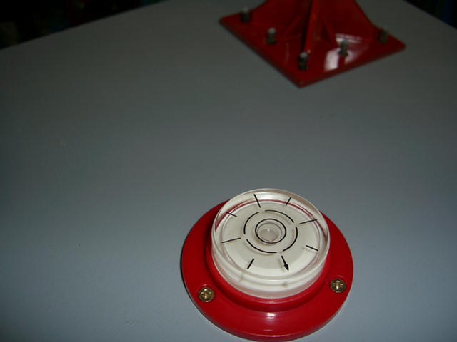
Will use this level to assure crane is level when in use.
Excuse me, but I have some more bolting to do. :)
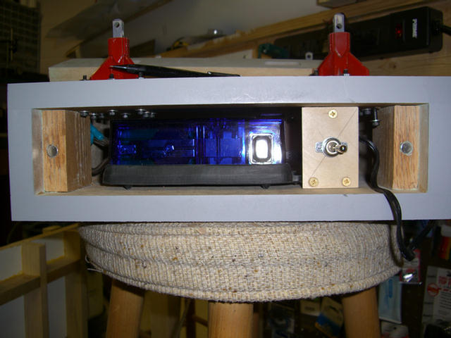
The two speed air compressor on the left and the on-off switch for it.
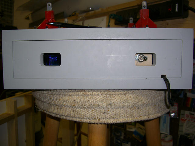
The on-off switch is accessible through the finger opening.
Patience Grasshopper............It will take a little time to load. Then it will play automatically.
It's mid April. I guess I should take the Christmas lights down.
(PS. Thanks Doc.)