Drive line
I have started the stuffing tube bearing housings. These will be supported by the brass strut arms connected to the hull.
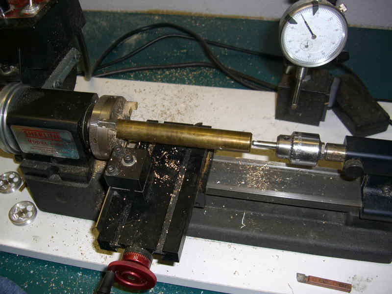
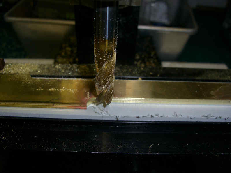
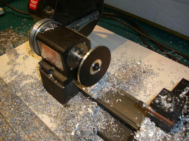
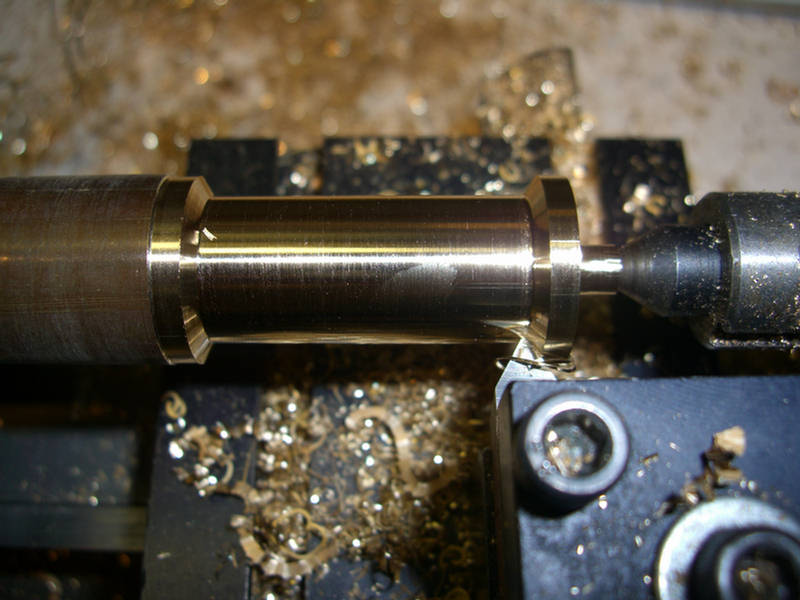
Stock centered in lathe, and being center drilled for rear center support
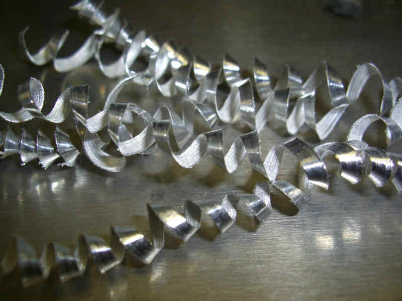
Making shavings out of expensive stock. I'm VERY good at this.

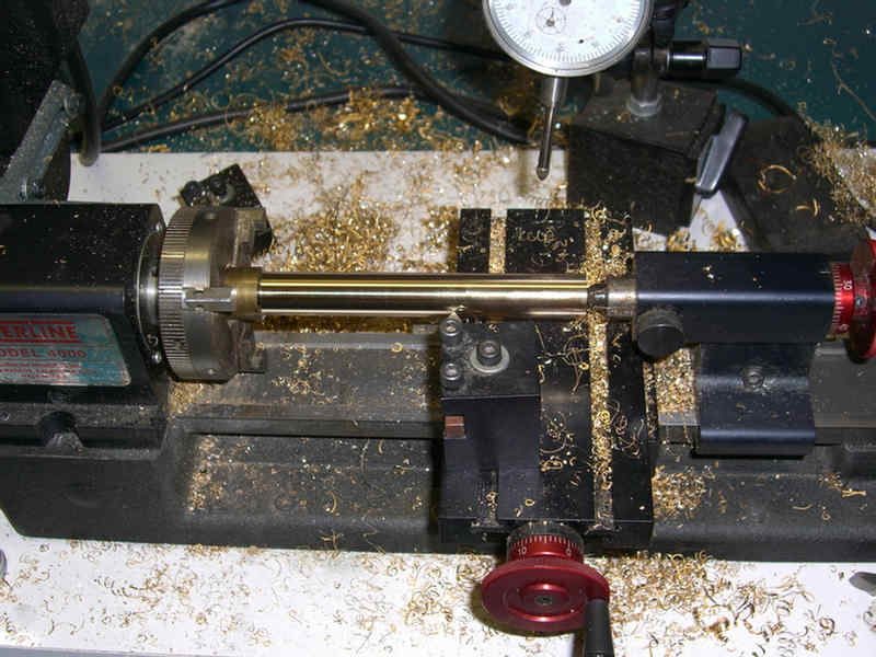
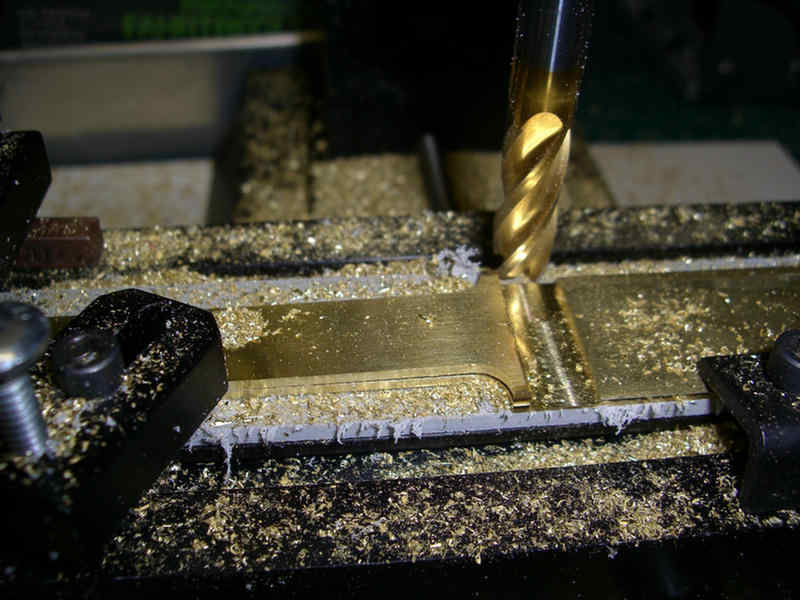
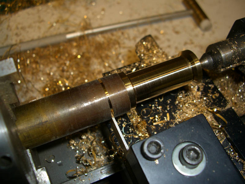
Just starting the cutoff cuts. Will not cut all the way through until required. Do as many machining process as possible on one set up. setting up a second time is just asking for degradation in accuracy.
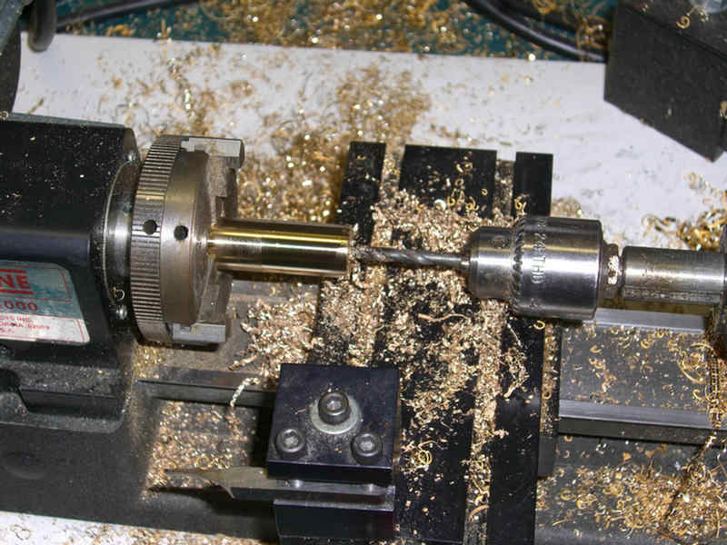
Drilling in center to allow inside cutting tool clearance.
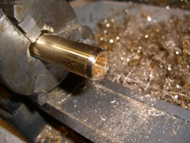
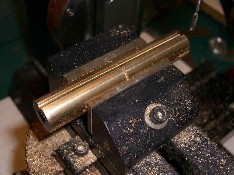
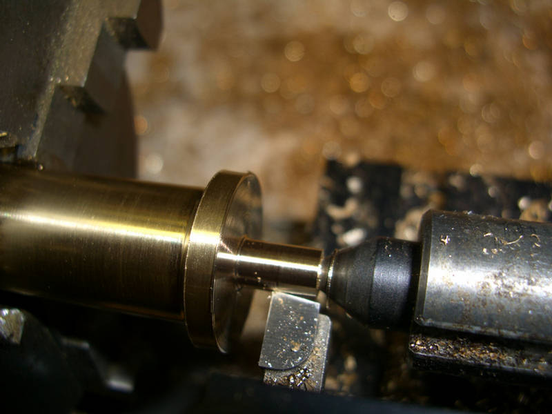
One of the housings with the inside cut to size and the bevel on the outside started.
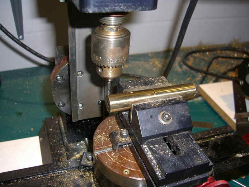
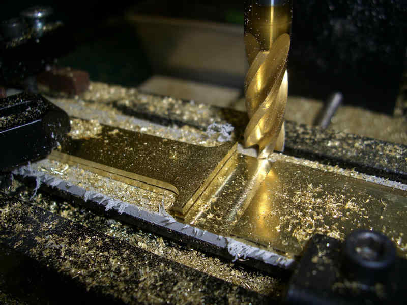
Now over to the milling machine to cut slots for the strut braces.
Slot is now to finished depth.
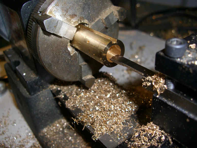
Inside bore being turned to finished size.
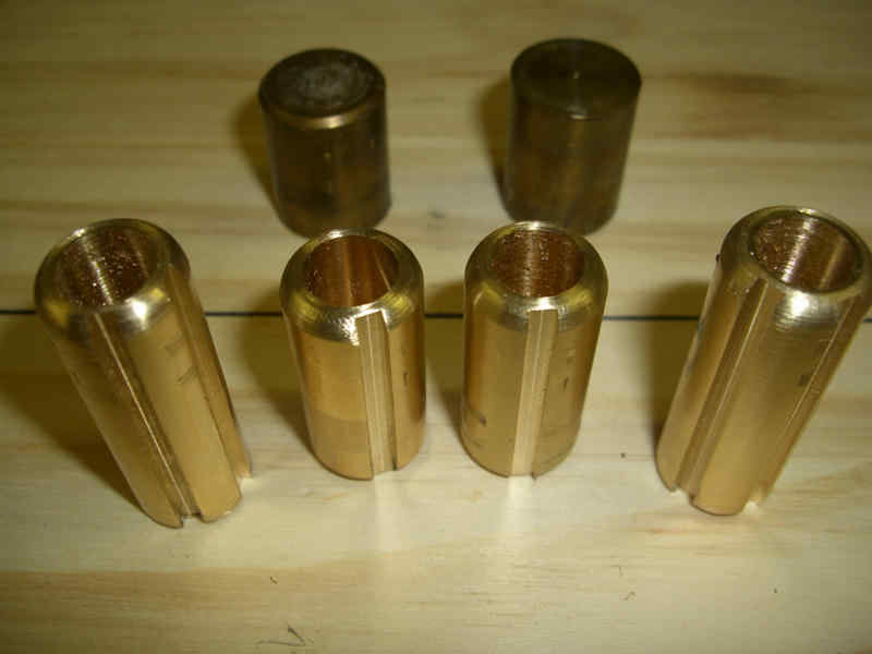
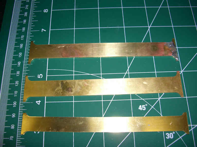
There you have them. A left, a right, and two that are the same. Will set these aside now until they are needed.
Glamour shot!!
Started on the struts. Will make them well longer than needed, then trim them when/if the hull ever arrives.
Location for the end of the prop shafts is affixed via a template.
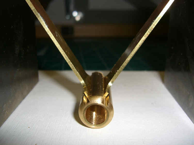
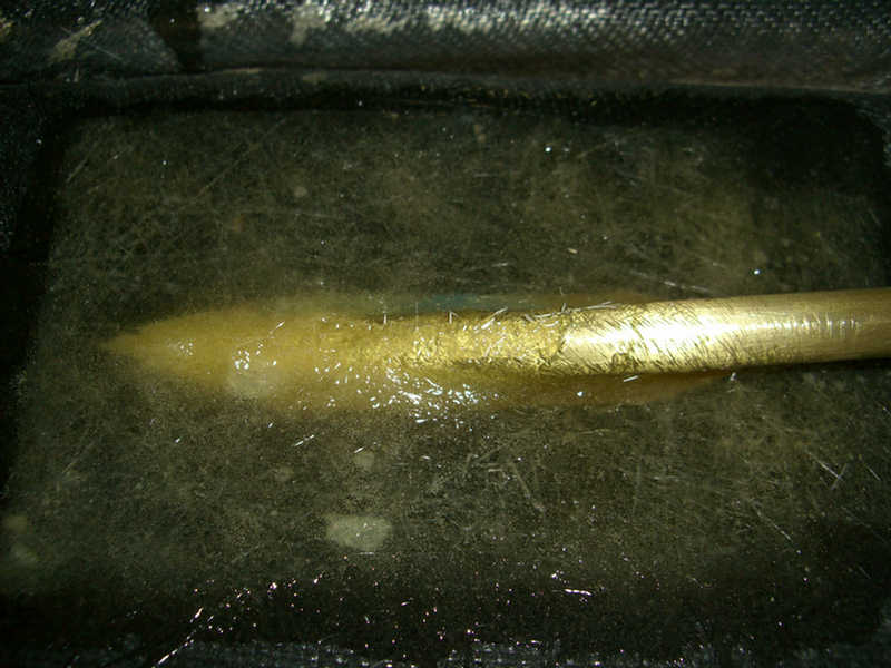
One of the struts just before silver soldering.
Strut soldered in place.
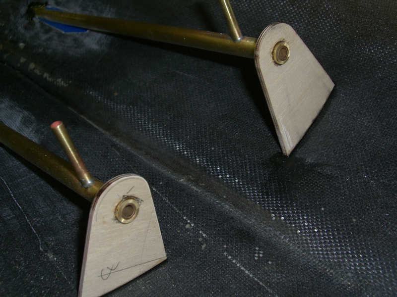
Struts and stuffing tubes loosely fitted. Will final fit when bearings and prop shafts are installed in the stuffing tubes.
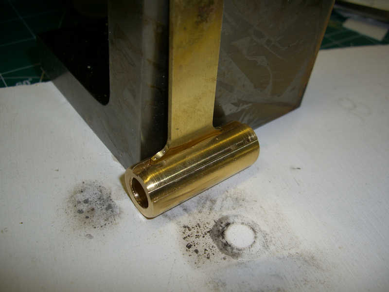
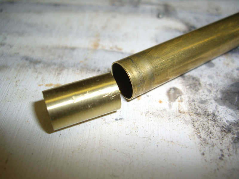
The stuffing tubes are too large to accommodate the bronze bushings. So, I need to make some brass tubes to size down each end of the stuffing tubes.
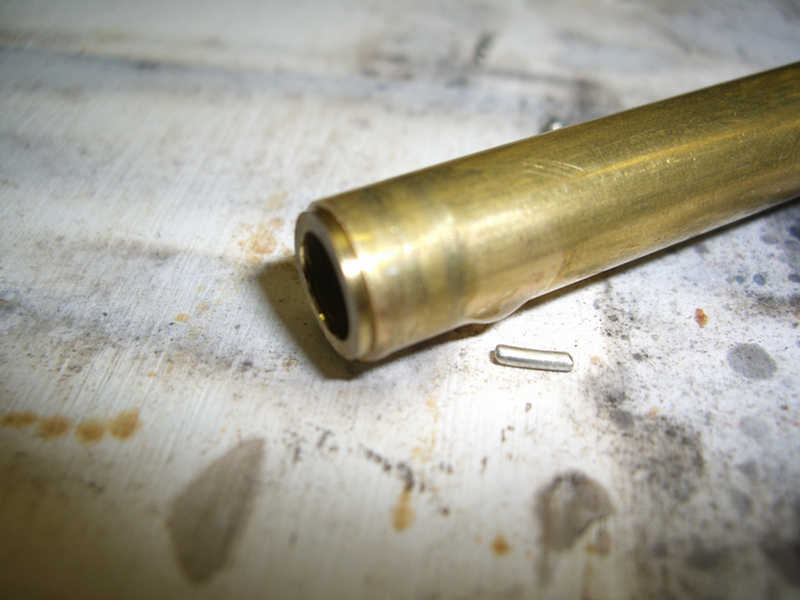
Here are the four tubes and a single bronze bushing. The actual stuffing tube is on the left.
Here are the completed tubes in place. Now they must be glassed in where they penetrate the hull.
These guys are now in this hull forever!
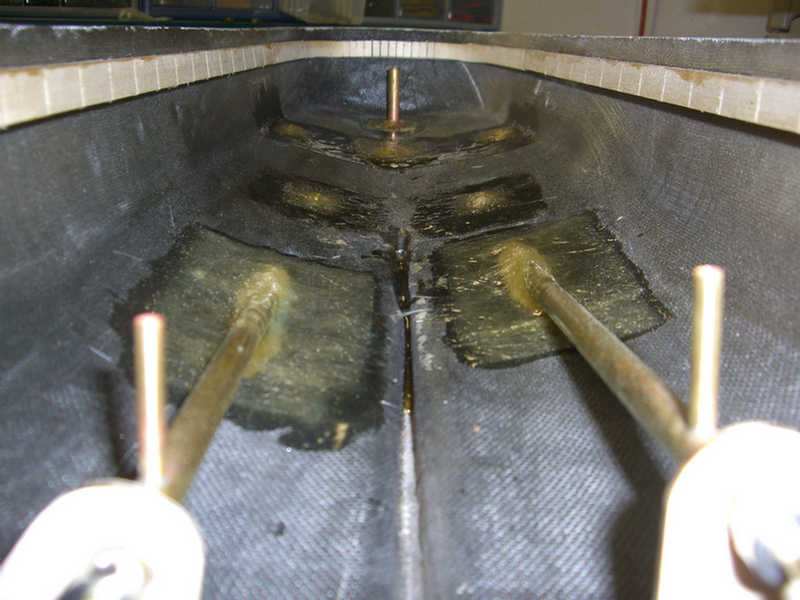
Tubes and the struts are now glassed in place. No twist to the rear of the hull, but a bulkhead will be placed in this area anyway.
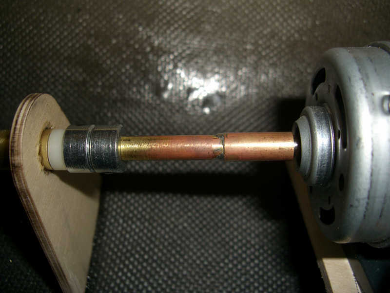
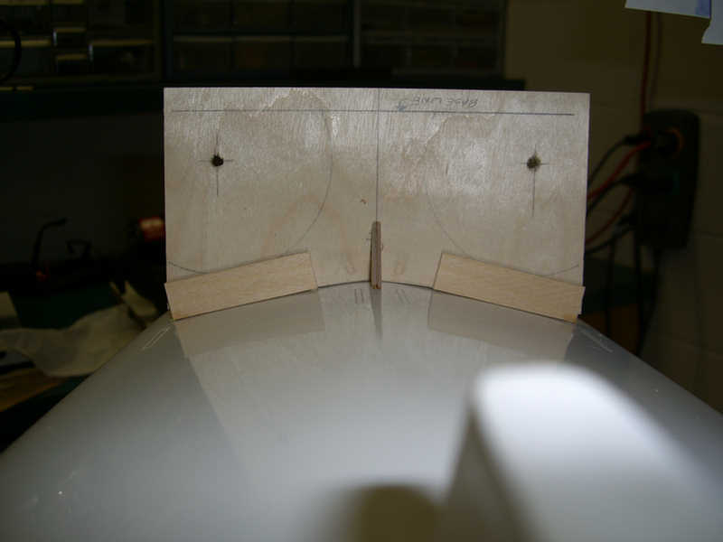
I mocked up the motor mount striving for perfect alignment. The jig is the same length as my universal joint will be. The jig is 3/16" dia. on one end to accommodate the propeller shaft, and 5mm on the other end to fit the motor shaft.
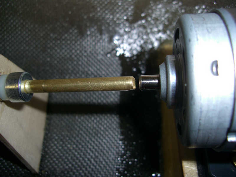
The result? A perfectly aligned shaft to minimize vibration.
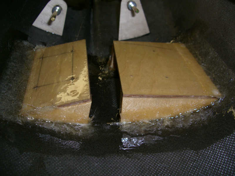
Next, the motor mounts are glassed in. Any bare wood must be sealed or it will eventually fail.
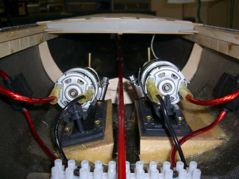
Motors mounted with a thin layer of foam to further reduce noise and vibration.
It's alive!
IT"S ALIVE!!!
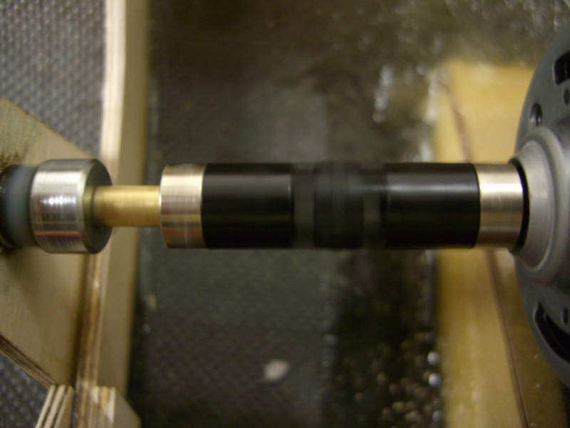
UPDATE: Well, its alive, but something is wrong. I used brass shafts because I could easily get brass in the lengths I needed for the shafts. The problem is that the shafts are whipping in the center of the stuffing tube in the unsupported middle between the front and rear bushings. The brass is somewhat flexible and the distance between the front and rear bushings is substantial on this size ship. Knowing this now means I should have added a third bushing in the center. This would not be easy to do at this time.
I have ordered and received ground stainless shafts long enough for this application. I installed the one on the port side and................................. No more whipping!! I then TRIED to install the starboard one and guess what??? It is too big in diameter to fit!!! I need .187" and when measuring this one it comes in at .192" Doesn't sound like much, but it's not going in a .187" hole. So, I have to send it back and get another one. Hope this time it fits.
FURTHER UPDATE: Another shaft arrived and measured in correctly at .187. Installation was a breeze when it is the right size.
ANCHOR WINDLASS
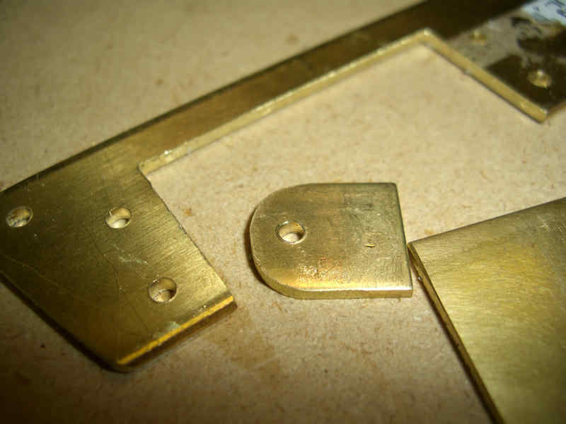
The start of the anchor windlass. Flanges will be turned out of anodized aluminum.
All that is left to do is install a switch to turn the windlass on and off.
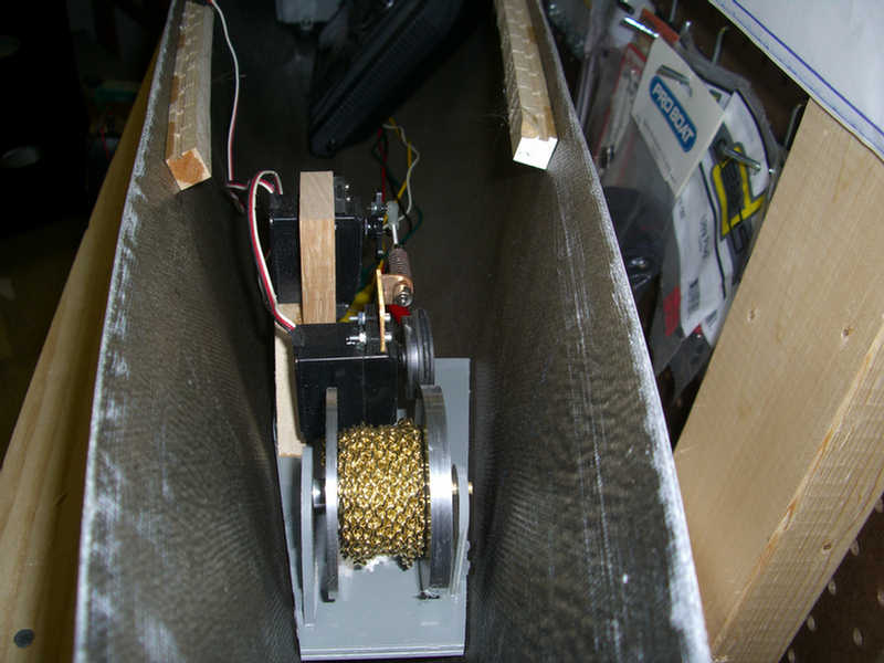
Test fitting of the unit in the hull.
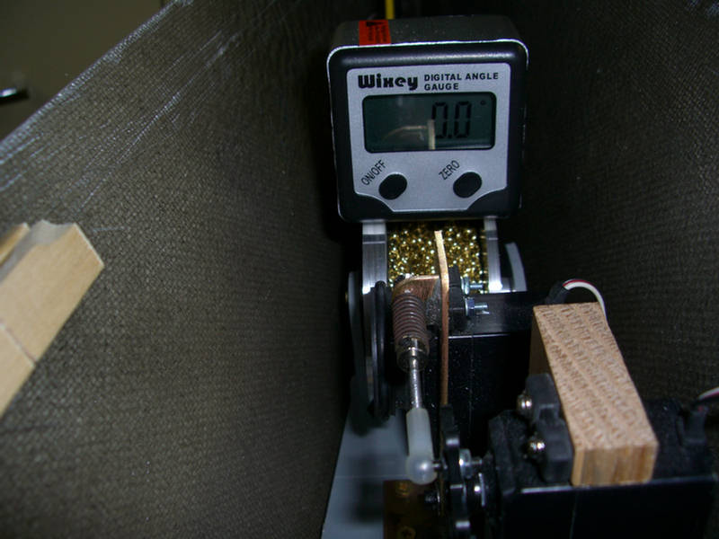
Check fit with digital angle gauge.
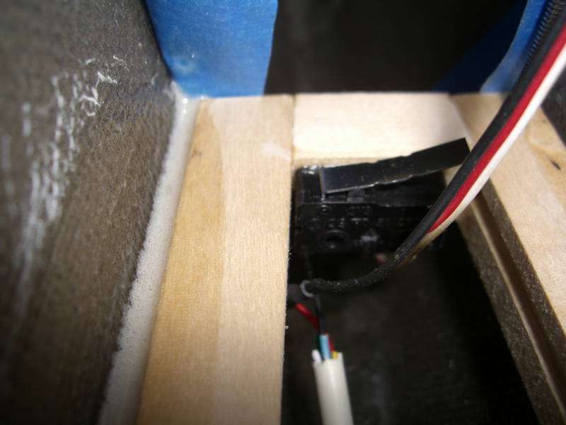
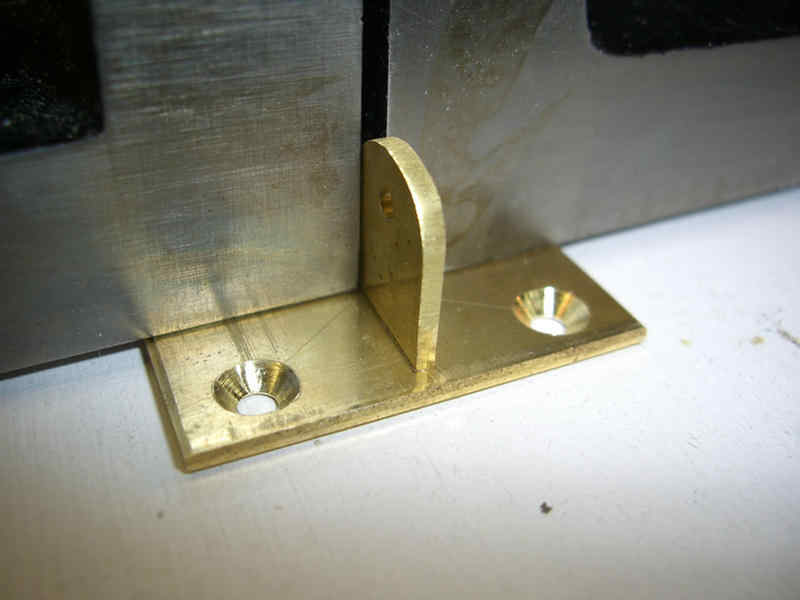
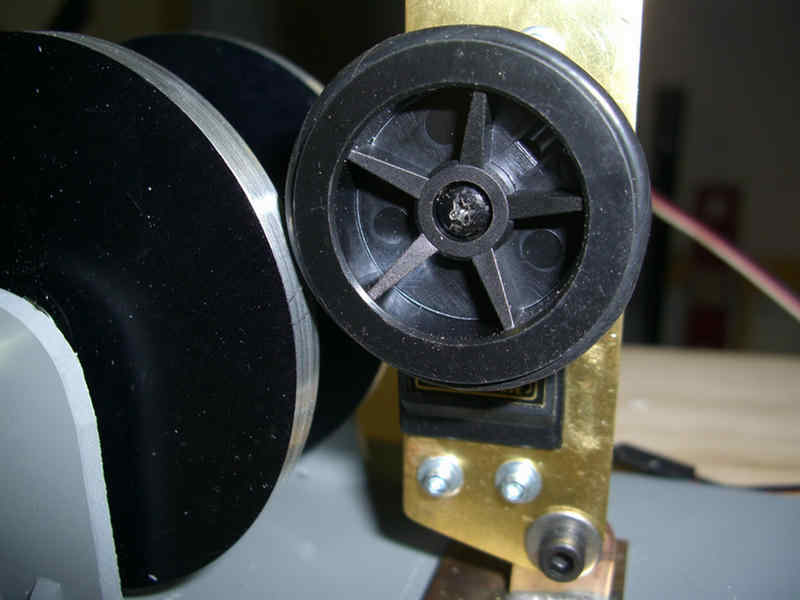
The frame for the anchor winch is installed. Note the micro switch. The frame is hinged on the opposite end from the micro switch. The threaded rod that you can just see to the right of the switch will have an adjustable spring to keep the front of the windlass pressed down against the micro switch. when too much tension is applied to the chain windlass, the windlass plate rises up and voltage is interrupted to the windlass motor. When I release the wheel against the windlass drum, the plate will come back down and close the micro switch allowing the chain windlass to turn again.
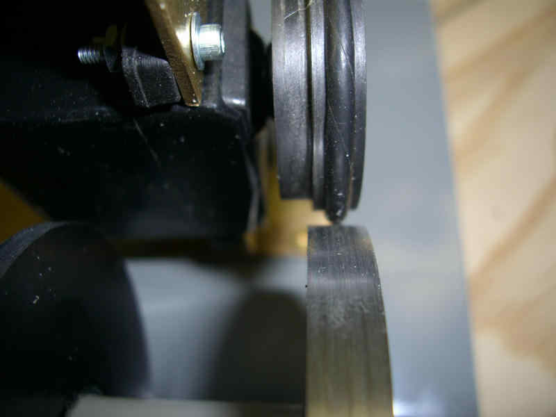
I need an idler drum to assure the chain pulls straight up on the chain windlass drum, allowing the micro switch to work properly.
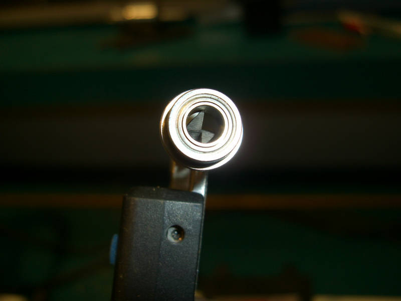
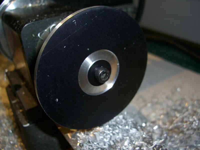
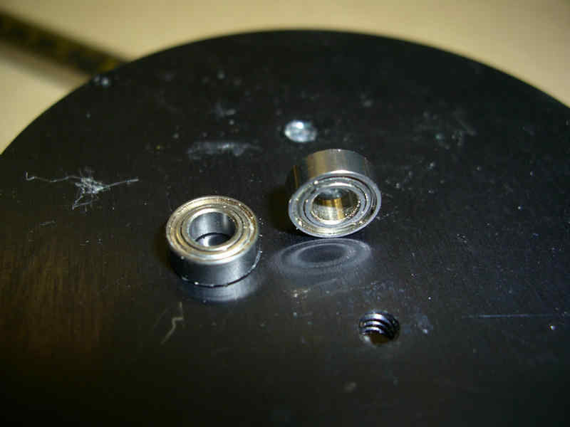
The idler drum must turn freely, so two 5mm x 10mm flanged bearings will be installed on each end of the idler drum.
Idler drum taking shape.
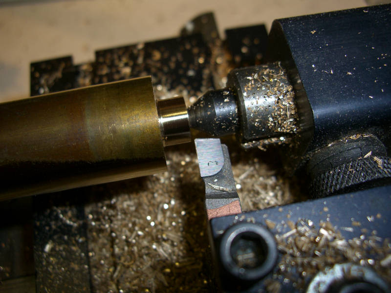
Cutting off the idler drum to reverse it in the chuck, in order to finish the other end.
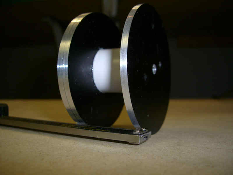
Final cut to achieve the 5mm diameter shaft for the bearing.
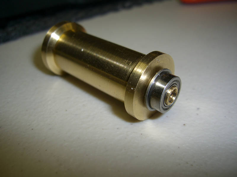
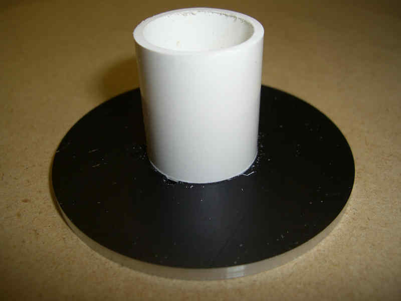
One idler drum ready to insert into the hull.
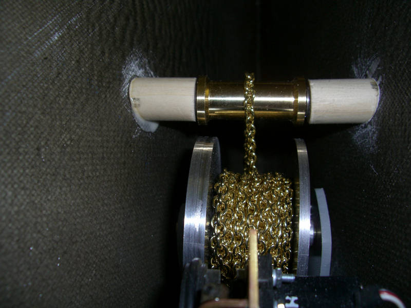
Here, the idler drum is installed in the hull.
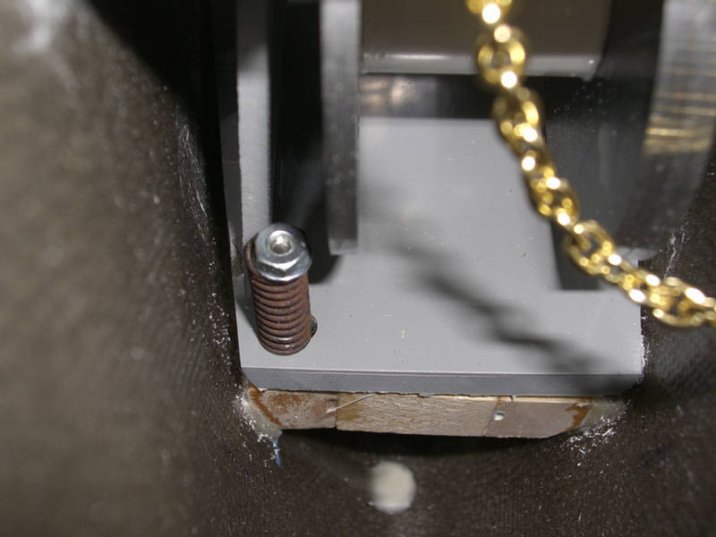
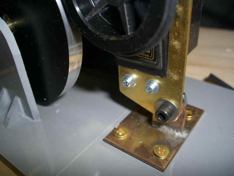
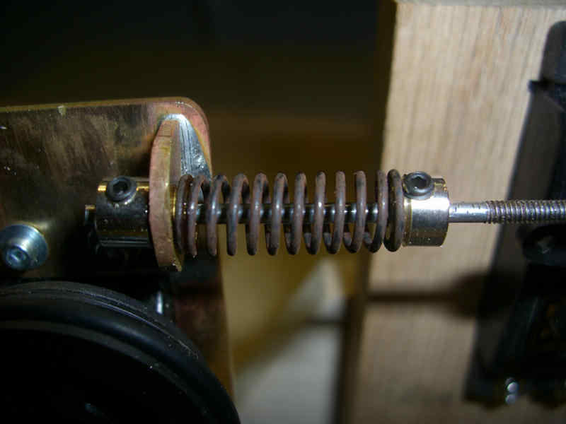
Here is the adjustable spring that will allow the front of the chain windlass plate to pivot up, thus opening the micro switch and subsequently shutting off power to the chain windlass motor.
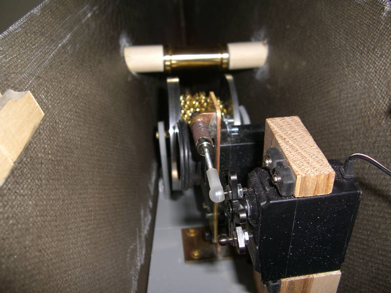
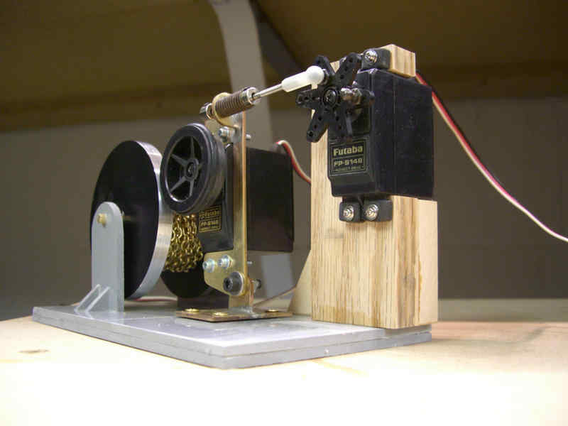
A little dusty, but here is the complete anchor windlass assembly installed in the hull.